A CNC hobbing machine is a precision gear manufacturing system that uses a rotating multi-tooth cutting tool — the gear hob — to progressively generate gear tooth profiles on a gear blank through a tightly synchronised multi-axis cutting motion. It is the dominant method for producing spur gears, helical gears, worm wheels, splines, and sprockets at production scale, combining high material removal rates with the gear accuracy required by automotive, industrial, and energy sector applications.
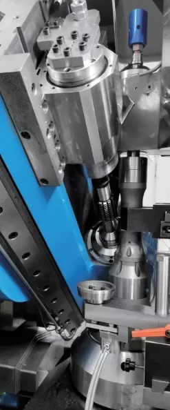
CNC hobbing in operation: hob and workpiece rotate in synchronised continuous mesh
How a CNC Hobbing Machine Works
The fundamental cutting principle of gear hobbing is continuous generation. The hob and workpiece rotate simultaneously in a precisely calculated speed ratio that mirrors the meshing relationship of the hob’s thread geometry with the gear tooth being produced. As the hob feeds axially across the face of the gear blank, each successive hob flute takes a small chip, and the cumulative effect of all cuts across one full workpiece rotation generates a complete gear tooth space — repeated around the full circumference of the blank.
On a modern CNC hobbing machine, this synchronisation is achieved entirely through the machine’s electronic gearbox — a software function in the CNC controller that maintains the precise B-axis to C-axis speed ratio continuously, compensating in real time for load variation, thermal expansion, and servo response lag. Earlier machines required physical change gears — sets of gear wheels whose tooth counts set the hobbing ratio — which had to be manually swapped between gear variants. The electronic gearbox eliminates this entirely: changing from a 35-tooth spur gear to a 42-tooth helical gear is a parameter entry in the CNC program, not a physical setup operation.
The Axes of a CNC Hobbing Machine
A modern CNC hobbing machine controls between six and seven axes simultaneously. Understanding what each axis does helps in evaluating machines and diagnosing production results:
| Axis | Function |
|---|---|
| B — Hob Spindle Rotation | Rotates the hob at the cutting speed. Direct-drive motors eliminate backlash in this axis. |
| C — Workpiece Table Rotation | Rotates the gear blank. Synchronised precisely with B-axis to generate the correct tooth count. |
| X — Radial Feed | Moves the hob toward the workpiece to achieve full depth of cut. |
| Y — Tangential Feed | Moves the hob along its own axis for hob shift strategies that extend tool life. |
| Z — Axial Feed | Feeds the hob across the face width of the gear blank during the cutting pass. |
| A — Helix Angle | Tilts the hob spindle to match the helix angle of the gear being cut. |
| U — Tailstock (7-axis machines) | Controls hydraulic tailstock positioning for shaft-type workpiece support. |
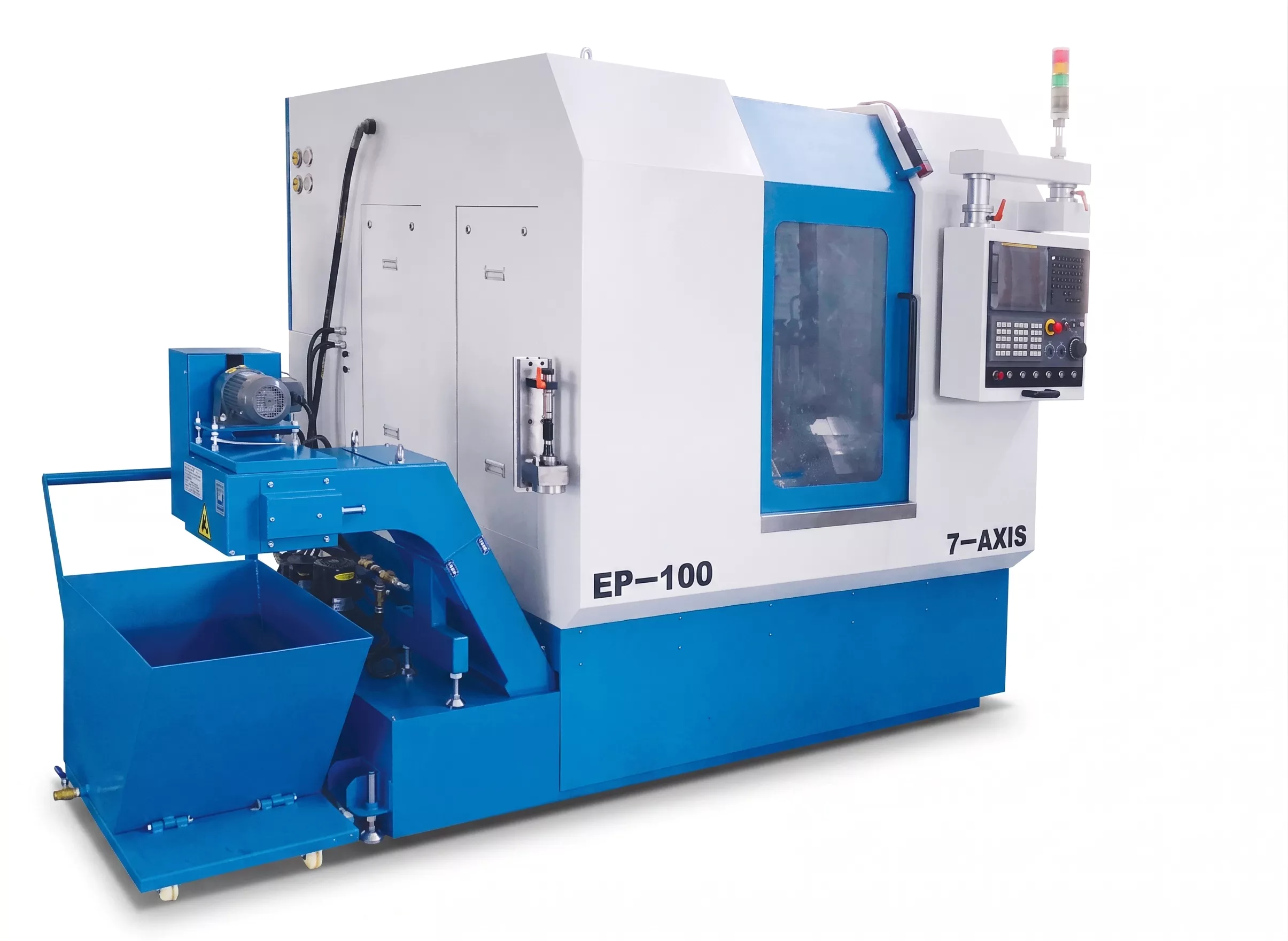
EP-100 CNC 7-Axis Horizontal Hobbing Machine — the horizontal configuration positions the workpiece axis horizontally, suited to smaller-diameter gears
Key Specifications to Evaluate on Any CNC Hobbing Machine
Maximum Module
The largest gear module (tooth size) the machine can cut. Smaller modules require higher spindle speeds and lighter cuts; larger modules require higher torque and more rigid structure.
⭕Maximum Workpiece Diameter
Determines the largest gear OD the machine can accommodate. This is typically the primary capacity spec used to categorise machines.
⚡Hob Spindle Torque (B-axis)
S1 rated torque determines sustained cutting capacity. S3 rated torque is the intermittent peak. Higher torque enables larger module cutting and harder materials.
Table Torque (C-axis)
The rotary table torque determines the workpiece holding force under tangential cutting loads. Low table torque causes micro-slip that degrades tooth spacing accuracy.
️CNC Control Platform
FANUC 0i-MF Plus, Siemens 840D, and Mitsubishi M80 are the dominant platforms. Control choice affects CAM compatibility, spare parts availability, and service support.
↔️Hob Shift Travel (Y-axis)
Longer Y-axis travel allows more aggressive hob shift strategies, distributing wear across the hob length and extending tool life between resharpenings.
Horizontal vs Vertical CNC Hobbing Machines
CNC hobbing machines are configured in two orientations: horizontal (workpiece axis horizontal) and vertical (workpiece axis vertical). Each has production advantages that make one preferable for specific gear families.
| Feature | Horizontal | Vertical |
|---|---|---|
| Chip Evacuation | Chips fall toward the hopper system; suited to inclined-bed designs | Chips fall by gravity clear of the cutting zone; better for larger module |
| Workpiece Loading | Easier for shaft-type components; tailstock support natural | Better for disc-type gear blanks; gravity assists clamping |
| Module Range | Typically small to medium module (M0.5 to M6) | Medium to large module (M2 to M14+) |
| Typical Applications | EV drivetrain gears, precision instruments, power tools | Automotive gearbox gears, industrial gearboxes, wind turbine gears |
| Helix Angle Range | Often wider (e.g. +65° / -90° on 7-axis horizontal) | Typically ±45° |
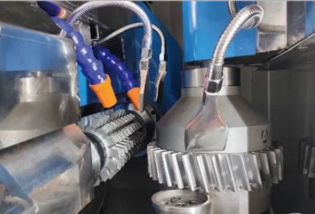
Vertical CNC hobbing machines: EP-200 (left, Phi 200mm / M6) and EP-350 (right, Phi 350mm / M8)
What Gear Accuracy Does CNC Hobbing Achieve?
CNC hobbing is a soft-cutting process — it machines the gear blank before heat treatment. Post heat treatment, gears that require DIN 5 or better accuracy are typically finished by CNC gear grinding. The achievable DIN class from hobbing alone depends on the machine quality, hob class, and process control:
| Process Stage | Typical DIN Accuracy Range |
|---|---|
| Hobbing only (soft, no subsequent grinding) | DIN 5 to DIN 9 depending on module and machine quality |
| Hobbing + shaving | DIN 5 to DIN 7 |
| Hobbing + gear grinding | DIN 4 to DIN 6 |
| Hobbing + skiving (hardened) | DIN 5 to DIN 7 depending on material |
For applications requiring DIN 5 or better on hardened gears — automotive transmissions, aerospace actuation, wind turbine gears — hobbing is the productive soft-cutting stage. The final DIN class is achieved in the subsequent grinding operation. See our article on CNC gear grinding machines for how the two processes work together.
Choosing the Right CNC Hobbing Machine for Your Application
The machine selection decision starts from three production parameters: the gear module, the workpiece diameter, and the annual production volume. These three define the required machine capacity, the hob spindle torque class, and the cycle time targets that determine whether a standard or high-speed configuration is needed.
For manufacturers across the automotive, industrial machinery, wind energy, marine, and mining sectors, our EP-series covers the complete range from M3 / Phi 100mm compact horizontal machines through to M14 / Phi 500mm large-capacity vertical configurations. Review the full range or submit your gear drawing for a direct application assessment via our engineering enquiry page.
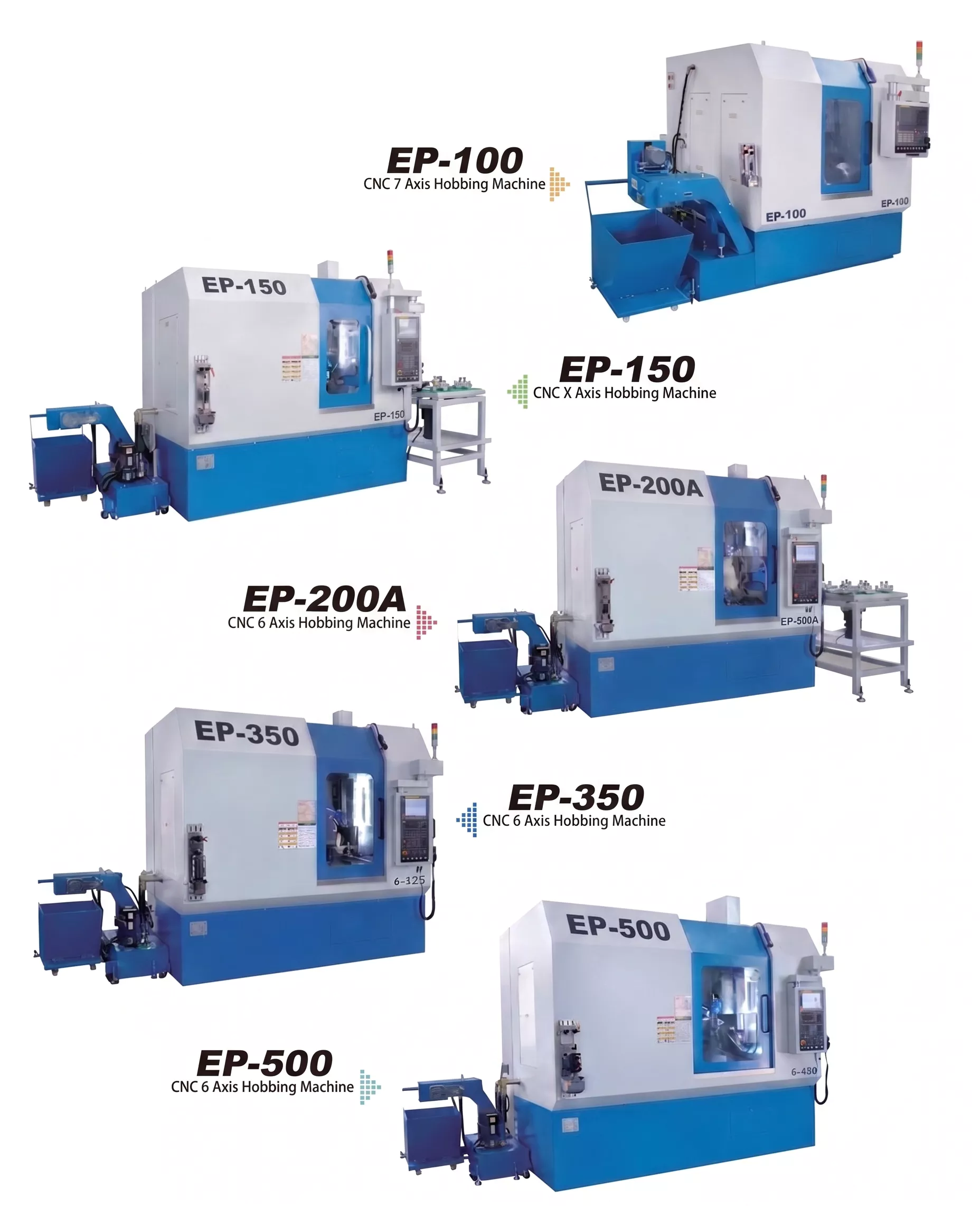
The complete EP-series CNC hobbing machine range
What is the difference between hobbing and gear grinding?
Hobbing is a soft-cutting process that generates gear tooth profiles on an un-hardened blank at high material removal rates. Gear grinding is a hard-finishing process applied after heat treatment to achieve the highest gear accuracy classes (DIN 4 to DIN 6). Most precision gear manufacturing uses both: hobbing to generate the tooth form, then grinding to achieve final accuracy on the hardened gear.
Can a CNC hobbing machine produce internal gears?
Standard CNC hobbing produces external gears — spur, helical, worm wheel, and spline. Internal gears are typically produced by CNC gear shaping. Some hobbing machines can be configured for internal hobbing with specialist tooling, but this is less common.
What materials can a CNC hobbing machine cut?
CNC hobbing can cut all standard gear steels (case-hardening steels, through-hardening steels, alloy steels), cast iron, aluminium alloys, copper alloys, and engineering plastics. HSS hobs are used for most steel applications; solid carbide hobs are used for fine-pitch precision gears and dry cutting of case-hardening steels at high speed.
Ready to specify a CNC hobbing machine for your gear production line? Submit your gear drawing, module range, and annual production volume for a direct machine configuration recommendation.