High-Speed CNC Hobbing Machines: Balancing Cycle Time and Gear Quality
In competitive gear manufacturing — especially automotive supply — cycle time is money. Every second shaved from a gear’s hobbing cycle translates directly to lower cost per piece and higher machine throughput. But speed without quality is worthless: gears that fail inspection or cause warranty returns destroy the savings many times over. High-speed CNC hobbing machines are designed to push cutting speeds to their maximum while preserving the gear quality that demanding customers require.
This guide examines what enables high-speed hobbing, how to find the optimal speed-quality balance for your specific application, and what machine features support both goals simultaneously.
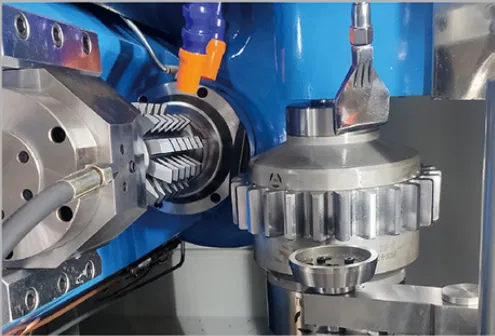
What Enables High-Speed Hobbing?
Achieving high cutting speeds in hobbing is not simply a matter of programming a higher RPM. It requires a system-level approach encompassing the machine, tooling, and process strategy:
Coated Carbide Hobs
Solid carbide hobs with advanced TiAlN or AlTiN coatings can run at 200–500 m/min surface speed — 3–5× faster than HSS hobs in wet hobbing. This is the single biggest enabler of high-speed hobbing in automotive production.
High-Rigidity Machine Structure
At high cutting speeds, dynamic cutting forces and vibration increase. A stiff machine structure (heavy cast iron or polymer concrete base, short, rigid axis configurations) suppresses vibration that would otherwise cause chatter marks and accuracy loss at speed.
Thermal Management
High-speed dry hobbing generates substantial heat in the machine structure. Machines designed for high-speed operation incorporate thermal decoupling (separating heat sources from the precision structure), active cooling of critical components, and CNC thermal compensation.
High-Speed Spindle Bearings
Hob spindle bearings must sustain high RPM continuously without excessive heat generation or premature wear. High-speed hobbing machines use precision angular contact bearings or hydrostatic spindle bearings with oil-air lubrication systems rated for sustained high-speed operation.
The Speed-Quality Trade-Off: Where Is the Limit?
Increasing cutting speed always involves trade-offs. Understanding these trade-offs lets you find the optimum operating point for your specific gear and quality requirements:
| Speed Increase Effect | Impact on Quality | Mitigation |
|---|---|---|
| Higher cutting temperature | Thermal expansion of machine and workpiece | Thermal compensation, warm-up cycles, MQL cooling |
| Higher centrifugal forces | Hob arbor deflection at high RPM | Shorter, stiffer arbors; balanced hob assemblies |
| Higher dynamic cutting forces | Increased vibration (chatter) | High-rigidity machine; optimized feed for chatter avoidance |
| Faster hob wear rate | Gear quality degrades as hob wears between shifts | Automatic hob shift; structured wear monitoring |
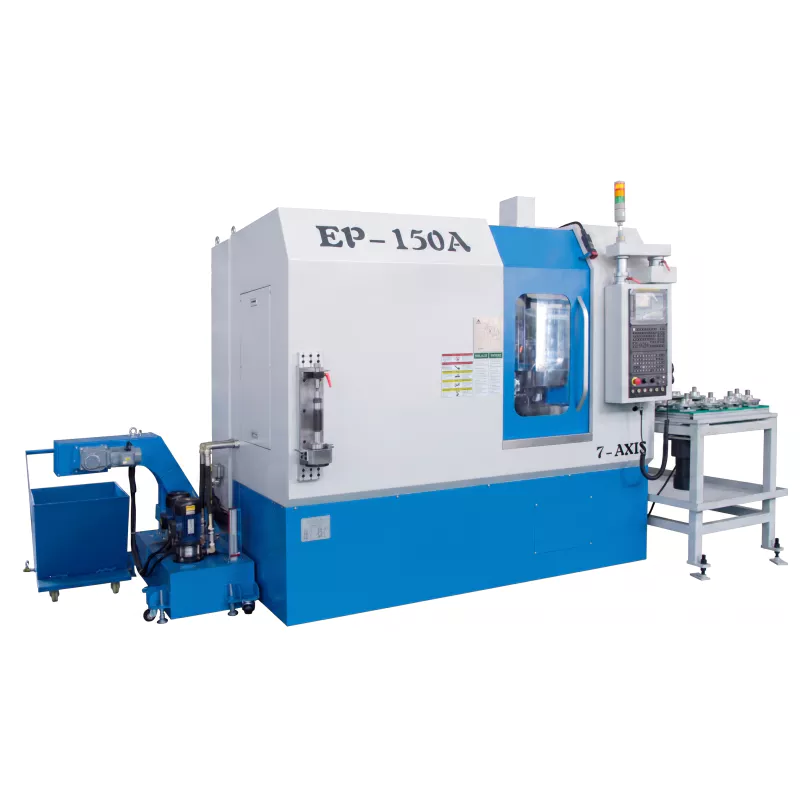
Practical Approach: Finding Your Optimal Speed
📈 Step 1 — Start With Tooling Manufacturer’s Recommendation
Your hob supplier’s cutting data is the best starting point. Their recommended cutting speed is based on extensive testing for your material and hob type. Use this as a safe starting point before optimization.
📈 Step 2 — Increase Speed in 10% Steps
After the initial baseline is established and gear quality confirmed, increase cutting speed by 10% and run a batch of 50–100 gears. Measure gear quality and hob wear. If both are acceptable, increase again. Stop when gear quality begins to degrade or hob wear rate increases unacceptably.
📈 Step 3 — Optimize Feed Rate at the New Speed
Once the optimal cutting speed is established, optimize axial feed rate — increase until surface finish or profile accuracy reaches the limit of your quality requirement. The combination of maximum safe speed and maximum safe feed gives minimum cycle time.
📈 Step 4 — Develop a Hob Life Model
At the optimized speed and feed, run a tool life study. Measure gear quality at regular intervals throughout the hob’s life. Establish a quality-based hob change criterion that ensures gears never go out of tolerance before the hob is replaced or shifted.
High-Speed Hobbing Performance Benchmarks
200–300 m/min
Typical automotive dry hobbing speed for m2 steel gears with TiAlN-coated carbide hobs
DIN 6–7
Achievable accuracy class at these speeds in optimized dry hobbing conditions
5–30 sec
Typical hobbing cycle time for automotive module-2 gears at optimized high-speed dry conditions
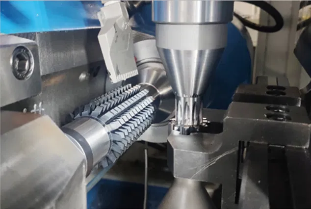
Our High-Speed CNC Hobbing Machine
Our CNC Hobbing Machine is designed for high-speed dry hobbing operations — with high-speed spindle options, rigid polymer concrete or cast iron machine beds, thermal management, and CNC thermal compensation. It delivers the cycle time your production requires without sacrificing the gear quality your customers demand.
👉 View High-Speed CNC Hobbing Machine →
👉 Discuss Your Speed and Quality Targets With Us →