How Does a CNC Hobbing Machine Work? The Gear Cutting Process Explained
If you have ever wondered exactly how a CNC hobbing machine transforms a cylindrical metal blank into a precision gear, this guide provides a clear, technical explanation of the entire gear cutting process — from the physics of the hobbing operation to the role of each machine axis and the CNC controller.
The Hobbing Principle: Generating Gear Teeth by Continuous Conjugate Motion
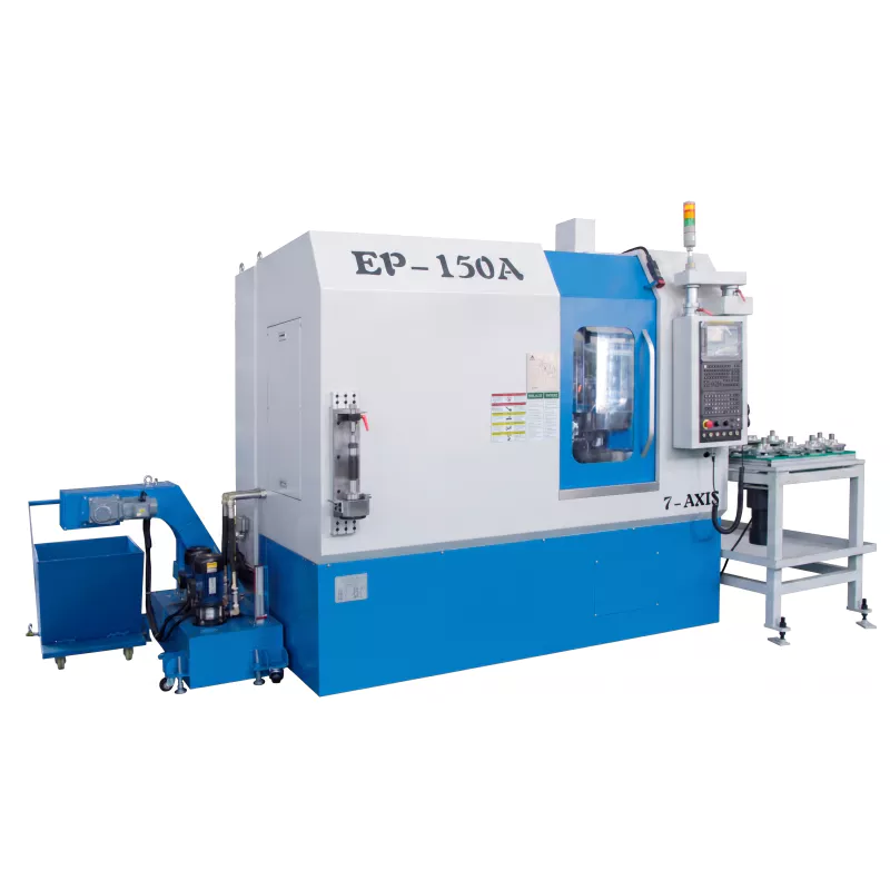
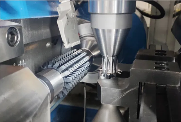
Gear hobbing is a generating process, not a form-cutting process. This distinction is fundamental. In form cutting (such as gear milling), the cutter is shaped to the exact tooth space profile and plunges directly into the blank. In hobbing, the tooth form is generated by the combined motion of hob and workpiece — no individual cut has the final tooth shape. Instead, each hob tooth takes a small chip, and the envelope of all the chips produces the correct involute profile.
This is why hobbing can produce theoretically perfect involute gear teeth with the same hob across a wide range of tooth numbers — a single module-2 hob can cut gears from 12 teeth to 200+ teeth. Only the synchronization ratio between hob and workpiece changes.
The Synchronized Rotation Relationship
The most critical aspect of hobbing is maintaining the correct synchronization ratio between the hob and the workpiece throughout the entire cut:
For example, to cut a 40-tooth gear with a single-start hob, the workpiece must rotate exactly 1/40 of a revolution for every complete revolution of the hob. The CNC controller enforces this ratio electronically through servo drives and high-resolution encoders on both spindles — with zero accumulated error over millions of cycles.
The Machine Axes and Their Roles
⚙ B-Axis — Hob Spindle Rotation
Drives the hob at the cutting speed (expressed in RPM or surface meters per minute). This is typically the highest-speed axis on the machine, often running from a few hundred RPM to several thousand RPM depending on hob diameter and cutting conditions.
⚙ C-Axis — Workpiece Spindle Rotation
Rotates the gear blank in exact synchrony with the hob (B-axis). The electronic gear ratio between B and C axes generates the gear tooth count. Any deviation from the programmed ratio results in pitch error in the finished gear.
⚙ X-Axis — Radial Feed (Depth of Cut)
Moves the hob spindle toward the workpiece to set the cutting depth. For full-depth cuts, the X-axis plunges to the programmed center distance. For multiple-pass cutting (roughing + finishing), the X-axis steps in stages.
⚙ Z-Axis — Axial Feed
Moves the hob axially across the gear face width during cutting. The axial feed rate (mm per workpiece revolution) is a key process parameter that affects surface finish, chip load, and cycle time. Finer feeds give better surface finish but longer cycle times.
⚙ A-Axis — Hob Head Swivel
Rotates the hob spindle axis relative to the workpiece axis. Set to the hob lead angle ± the gear helix angle. This ensures the hob thread helix is properly aligned with the gear tooth helix during cutting. Incorrect swivel angle produces helix error.
⚙ Y-Axis — Hob Shift (Tangential)
Shifts the hob tangentially to bring fresh cutting teeth into the active zone. Automatic hob shift, programmed to shift by a specific amount after each gear or batch, extends hob life dramatically by distributing wear across all hob teeth rather than concentrating it on a few.
Climb vs. Conventional Hobbing
▼ Climb (Down) Hobbing
Hob rotates so teeth enter the cut from the top and exit at the bottom. Chip thickness decreases through the cut. Produces better surface finish, lower cutting forces. Preferred for finishing cuts and in modern high-speed hobbing.
▲ Conventional (Up) Hobbing
Teeth enter from the bottom and exit at the top. Chip thickness increases through the cut. Historically used for roughing. Can cause built-up edge on the hob at low speeds. Less common in modern CNC hobbing.
Radial vs. Tangential Infeed for Worm Wheels
When hobbing worm wheels, two infeed methods are used:
- ● Radial infeed: The hob feeds radially to full depth, then feeds tangentially across the face. Suitable for standard worm wheels.
- ● Tangential infeed (axial): The hob is pre-set at full depth, then fed axially past the worm wheel. Produces more accurate tooth form. Required for precision worm wheel sets.
Our CNC Hobbing Machine
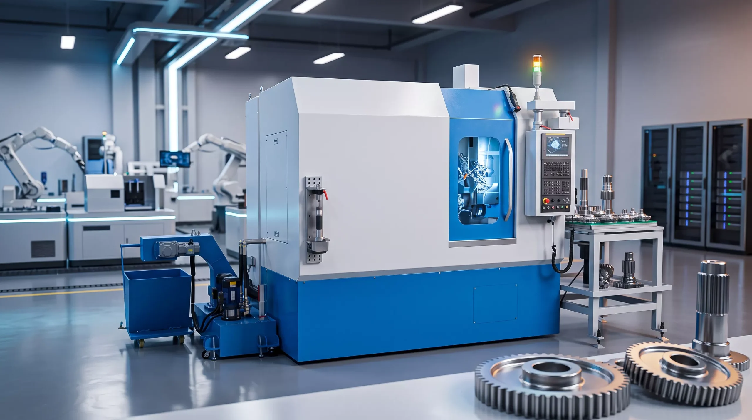
Our CNC Hobbing Machine embodies the full range of hobbing capabilities described in this guide — multi-axis servo control, precise electronic gearing, automatic hob shift, and compatibility with both wet and dry cutting strategies. It is ready to deliver the gear quality your application demands.
👉 Learn More About Our CNC Hobbing Machine →
👉 Contact Us for Technical Consultation →
Partner With Our Gear Cutting Experts
Understanding how a CNC hobbing machine works is the first step to optimizing your gear manufacturing process. Our technical team can assist with process parameter selection, hob tooling recommendations, and machine specification to ensure you achieve the gear quality and production rates your application requires.