CNC hobbing machine selection is often led by the wrong criteria — headline price, maximum spindle speed, or the brand name of the CNC control — rather than the specification parameters that actually determine whether the machine produces your gears at the required accuracy, at the required cycle time, and at a per-part cost that makes your production viable. This article identifies the eight specification parameters that matter most in hobbing machine selection, what each one means in production terms, and how to use them to compare machines across different suppliers.
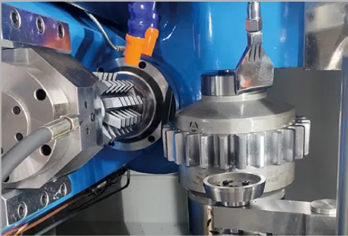
Machine selection starts from your gear geometry and accuracy requirement — not from the machine price list
Parameter 1: Maximum Module
Maximum module is the single most important capacity parameter. It determines the largest gear tooth size the machine can cut, which is set by the combination of hob spindle torque, structural rigidity, and table torque. A machine specified at M6 cannot reliably cut M8 gears — not because it physically cannot make the cut, but because the cutting forces at M8 will deflect the structure, overload the spindle, or cause table slip, all of which degrade accuracy.
Always specify the machine for your largest module requirement plus a 20% margin. If your current largest module is M6 but you anticipate M8 applications in future, specify an M8-rated machine now — retrofitting a machine for a larger module capability is not possible.
Parameter 2: Maximum Workpiece Diameter
Maximum workpiece diameter determines the largest gear the C-axis table and machine enclosure can accommodate. This is typically limited by the table diameter, the machine column clearance, and the enclosure size. Note that maximum workpiece diameter and maximum module are not directly linked — a machine might accept Phi 350mm workpieces but only to module M8, because the table torque required to cut M12 at that diameter is beyond what the machine provides.
Parameter 3: C-Axis Table Torque
Table torque is the specification most commonly underweighted in machine selection — and the one that most commonly causes production problems. The C-axis table must resist the tangential component of the hobbing force throughout every revolution of the workpiece. At module M4 in alloy steel, this force is substantial. If the table torque is insufficient, the workpiece will micro-slip against the table’s holding force during heavy cuts, producing periodic pitch error at the tooth-to-tooth level that no amount of programming adjustment can correct.
| Module Range | Minimum Recommended C-Axis Table Torque |
|---|---|
| M0.5 to M3 (fine-pitch) | 60 Nm to 200 Nm — EP-100: 60 Nm direct drive |
| M3 to M6 (medium) | 400 Nm to 800 Nm — EP-150: 600 Nm direct drive |
| M6 to M10 (heavy) | 800 Nm to 1500 Nm — EP-350: 1000 Nm direct drive |
| M10 to M14 (large) | 1500 Nm to 2500 Nm — EP-500: 2000 Nm direct drive |
Parameter 4: B-Axis Hob Spindle Torque and Speed
The B-axis specification is typically given as maximum speed and S1/S3 rated torque. S1 torque is the continuous rated torque — the torque the spindle can sustain indefinitely. S3 torque is the intermittent rated torque — typically 40% to 60% higher, sustained for short periods (the “S3” designation refers to a specific duty cycle standard). For roughing cuts and high-feed applications, S3 torque determines the maximum cutting depth before thermal derating. For sustained multi-pass finishing, S1 torque is the operative limit.
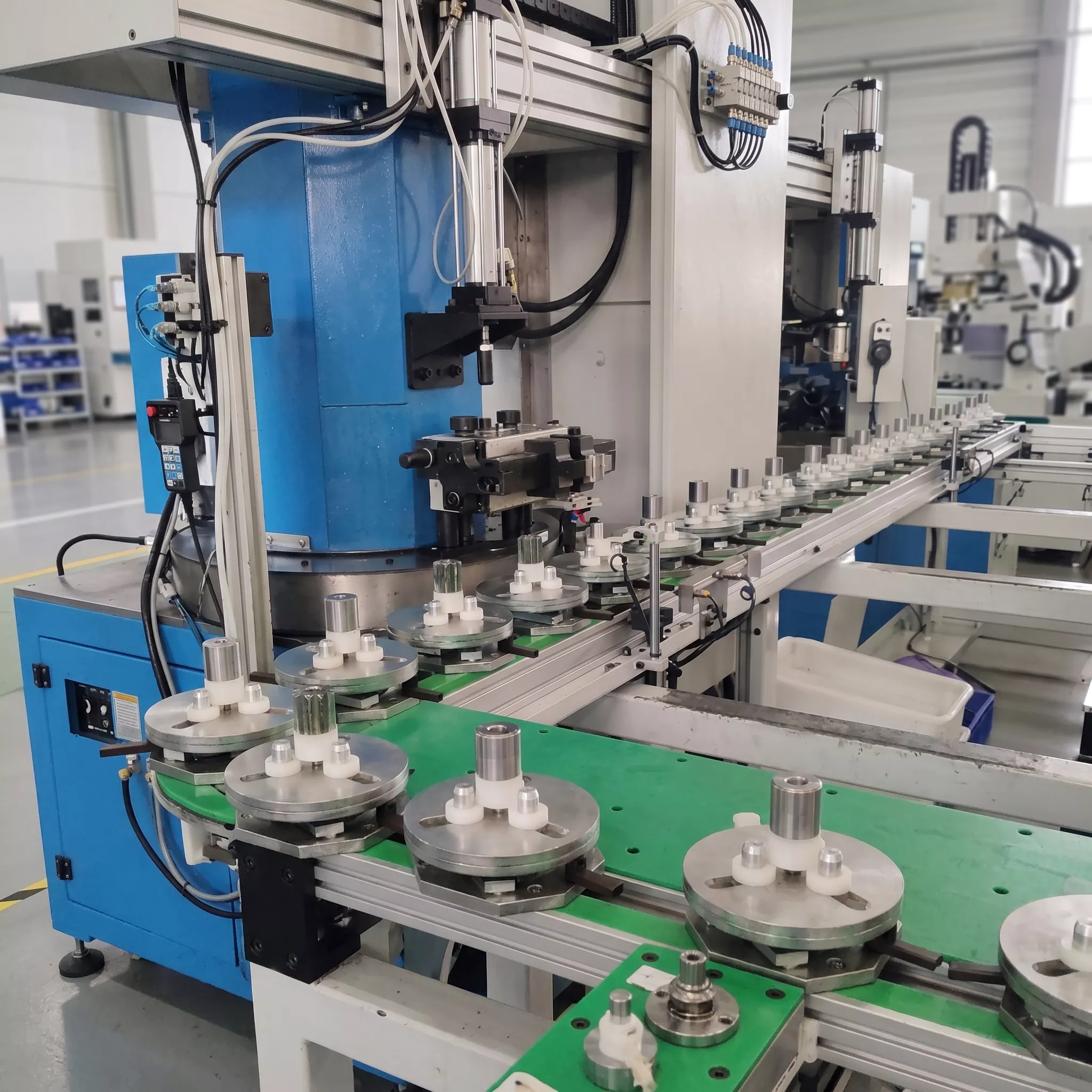
B-axis spindle (left) and C-axis table (right): the torque ratings of both axes must be matched to your module range
Parameter 5: Drive System Type — Direct-Drive vs Gear-Driven
The drive system type for both B-axis and C-axis is one of the most consequential machine selection decisions — and one that is rarely prominent in supplier specification sheets. There are two approaches:
✅Direct-Drive (Motor Directly on Spindle/Table)
The motor rotor is directly attached to the spindle or table — no gearbox, belt, or coupling in the transmission path. Advantages: zero mechanical backlash in the drive train, no speed ripple from gear tooth meshing, higher servo bandwidth for better synchronisation accuracy. Disadvantage: motor cost is higher; spindle speed is limited by motor characteristics rather than a gearbox step-up ratio.
⚠️Gear-Driven or Belt-Driven
An intermediate transmission connects the motor to the spindle or table. Advantages: can achieve higher spindle speeds from a lower-rpm motor; lower initial cost. Disadvantages: introduces mechanical backlash and periodic speed ripple at gear mesh frequency — both of which produce measurable pitch and profile deviation on the gear being cut.
For DIN 6 and better production, direct-drive B and C axes are effectively a requirement. The periodic profile deviation generated by gear-mesh-frequency speed ripple in a gear-driven spindle produces a systematic tooth form error at hob-rotation frequency that limits the achievable profile class.
Parameter 6: Hob Shift Travel (Y-Axis)
The Y-axis tangential feed is the axis that shifts the hob along its own spindle axis during or between cuts — also called hob shifting. Longer Y-axis travel allows more aggressive hob shift strategies that distribute wear across a longer section of hob length, increasing the number of parts produced between hob changes. On high-volume production lines, hob life is a significant element of per-part cost. A machine with 180mm of Y-axis travel (such as the EP-150 through EP-350) allows substantially more aggressive shift strategies than a machine with 80mm of Y-axis travel.
Parameter 7: CNC Control Platform
The CNC control platform determines CAM post-processor compatibility, spare parts and service availability, upgrade path, and the learning curve for your operators. The three dominant platforms in the global CNC hobbing market are:
| Platform | Strengths | Considerations |
|---|---|---|
| FANUC 0i-MF Plus | Global service network, widely understood, large post-processor library, proven reliability in production environments | Lower maximum axis count in base configuration; some advanced functions require optional packages |
| Siemens 840D sl | High configurability, excellent multi-axis synchronisation performance, strong in European automotive supply chains | Higher initial cost; more complex programming environment; smaller global service footprint than FANUC |
| Mitsubishi M80 | Cost-competitive, good synchronisation performance, strong in Asian automotive markets | Smaller global service footprint; fewer available post-processors in Western markets |
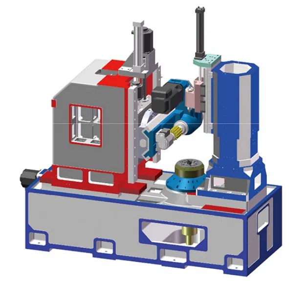
FANUC 0i-MF Plus: the control platform standard across the EP-series, providing maximum global service support and CAM post-processor availability
Parameter 8: Thermal Stability Features
Thermal stability is the specification parameter most commonly omitted from supplier comparison sheets and most commonly responsible for production quality problems after installation. As a CNC hobbing machine runs, heat generated by spindle motors, feed axis motors, coolant pump motors, and the cutting process itself raises the temperature of the machine structure. This temperature rise causes differential thermal expansion that shifts the relative position of the hob and workpiece — changing the cutting depth and the Z-axis position and producing systematic variation in the gears produced at the end of the shift compared to those produced at the start.
Two approaches address this: passive temperature management (spindle oil cooling, enclosure temperature control, warm-up cycles) and active thermal compensation (real-time temperature measurement and CNC-applied positional correction). Active thermal compensation — as incorporated in the EP-150 — eliminates the need for warm-up cycles and operator re-zeroing between shifts, and is particularly valuable for automotive production where Cpk targets apply across the full production shift, not just to individually sampled parts.
Combining the Eight Parameters: A Selection Worksheet
Use this table as a starting point for any CNC hobbing machine selection process:
| Parameter | Questions to Answer Before Comparing Machines |
|---|---|
| Max Module | What is the largest module in my current and anticipated gear family? |
| Max Workpiece Diameter | What is the largest gear OD I need to produce? |
| C-Axis Table Torque | What table torque is required for my module and material combination? |
| B-Axis Torque / Speed | What hob speed and torque does my module and hob diameter require? |
| Drive System Type | Does my DIN class requirement demand direct-drive B/C axes? |
| Hob Shift Travel | What Y-axis travel do I need to achieve my hob life targets? |
| CNC Control | Which control platform is already established in my facility? |
| Thermal Stability | Does my production run length and Cpk target require active thermal compensation? |
Before finalising any machine specification, request a sample machine acceptance test report showing CMM-measured gear results on a test gear at the stated DIN class. A supplier who cannot provide this documentation has not verified their claimed accuracy on production gears. All EP-series machines are supplied with a full acceptance test report covering the key gear accuracy parameters.
Should maximum spindle speed be a key selection criterion?
Maximum spindle speed matters for fine-pitch gear production (M0.5 to M2) where high cutting speeds are needed for productive carbide hob operation. For M4 and above, maximum spindle speed is rarely the limiting factor — table torque and structural rigidity become the binding constraints. Do not pay a premium for spindle speed you will not use.
Is floor footprint an important selection criterion?
Floor footprint matters when space is genuinely constrained, but it should not override the fundamental capacity parameters. A machine that fits the floor but cannot achieve your required DIN class or cannot handle your module range is not a viable solution regardless of its footprint.
How important is the machine weight in selection?
Machine weight is an indirect indicator of structural rigidity. A heavier casting generally provides better damping of cutting vibration and better thermal mass for stability — particularly important at larger modules. When comparing two machines of similar specified capacity, the heavier machine is typically the more rigid one.
Ready to apply these eight parameters to your specific gear family? Submit your gear drawing, module range, required DIN class, and production volume for a machine selection recommendation from our engineering team.