Gear accuracy is the central purchasing criterion for any CNC hobbing machine, yet it is frequently misunderstood. When a machine supplier quotes “DIN 6 accuracy,” what exactly is being measured? Which parameters are included? And what determines whether your production process — not just the machine — achieves that class consistently on every part? This article covers the DIN gear accuracy classification system, the individual parameters that define each class, the factors that most commonly limit achievable accuracy in production, and how to match machine specifications to your accuracy requirements.
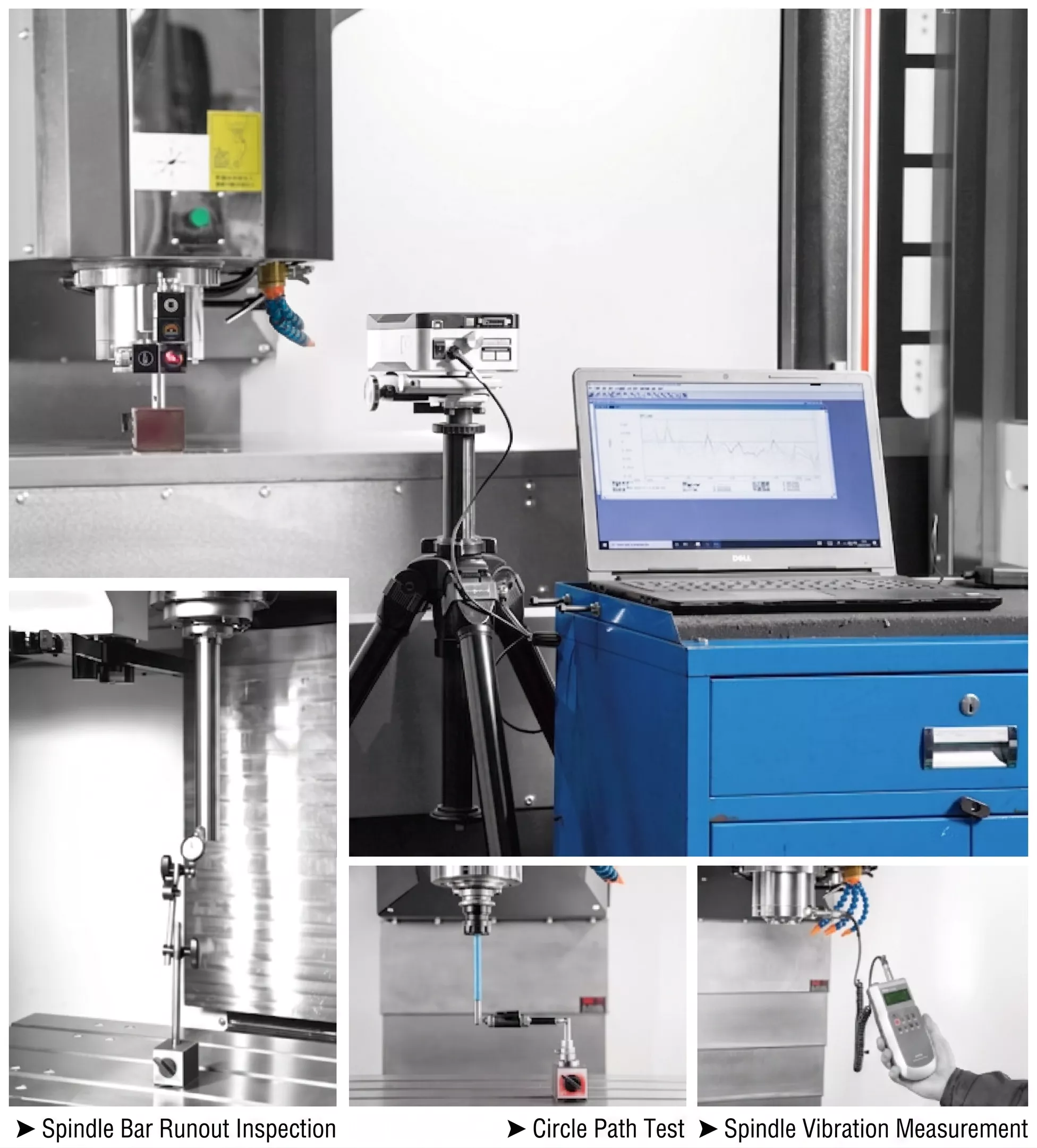
Gear CMM inspection: profile deviation (ff, Ff), lead error (fh, Fh), and pitch deviation (fu, fp, Fp) are measured and documented for every batch
The DIN Gear Accuracy Classification System
DIN 3962 and DIN 3963 define the gear accuracy classification system used across European and international gear manufacturing. Accuracy is expressed as a DIN class number from 1 to 12 — lower numbers mean tighter tolerances and higher accuracy. DIN 1 is the highest achievable (research and metrology applications only); DIN 12 is the coarsest class used in low-precision drives.
The DIN class system defines tolerance bands — not absolute values — for multiple individual gear parameters. A gear achieves a given DIN class only if all of its measured parameters fall within the tolerance band for that class. Meeting DIN 6 on tooth profile but DIN 8 on pitch means the gear is classified DIN 8.
The Six Parameters That Define DIN Gear Accuracy Class
| Parameter | Symbol | What It Measures |
|---|---|---|
| Profile Form Deviation | ff | Deviation of the actual tooth profile from the theoretical involute within the active profile band |
| Profile Slope Deviation | fHα | Angular difference between the actual and theoretical involute profile — relates to tip/root engagement |
| Lead Form Deviation | ffβ | Deviation of the actual lead (tooth contact trace along face width) from the theoretical helical form |
| Lead Slope Deviation | fHβ | Angular difference between the actual and theoretical lead — relates to end-face loading distribution |
| Single Pitch Deviation | fp | Deviation of the actual pitch between adjacent teeth from the theoretical circular pitch |
| Total Cumulative Pitch Deviation | Fp | Maximum range of cumulative pitch deviation measured around the full gear circumference |
In practical production monitoring, these six parameters are typically reported as part of a gear measurement report from a CMM gear measuring machine. The report lists the measured value for each parameter, the DIN class tolerance band it falls within, and the overall gear DIN classification based on the worst-performing parameter.
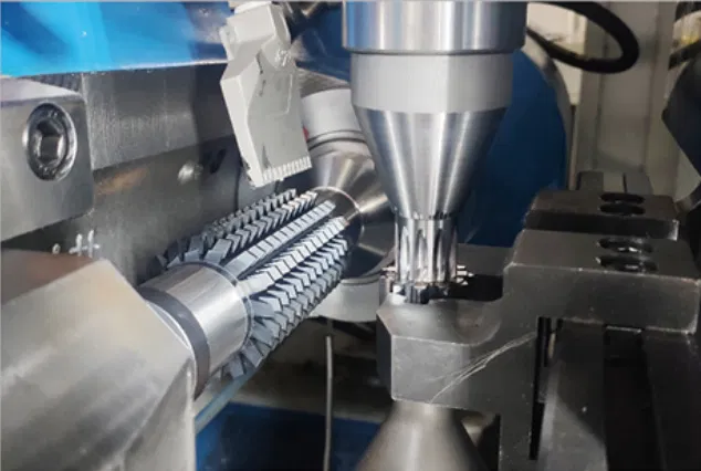
EP-150: active thermal deformation prevention maintains DIN class consistency from first part to last part of every shift
What DIN Class Is Achievable from CNC Hobbing?
The achievable DIN class from a CNC hobbing machine depends on five interrelated factors: machine accuracy, hob quality, process control, workpiece material condition, and thermal stability. Here is the practical relationship between machine quality and hobbing output:
| Machine Quality Level | Typical Achievable DIN Class (Soft Hobbing) |
|---|---|
| Research / ultra-precision hobbing | DIN 3 to DIN 5 |
| Production CNC hobbing — direct-drive, Class AA hob | DIN 5 to DIN 6 |
| Production CNC hobbing — standard quality, Class A hob | DIN 6 to DIN 7 |
| Older / lower-precision CNC hobbing | DIN 7 to DIN 9 |
These accuracy values refer to the soft (pre-hardened) gear. Case hardening and quenching introduces distortions that typically degrade the DIN class by 2 to 4 classes. A gear hobbed to DIN 5 typically emerges from case hardening at DIN 7 to DIN 9, before hard finishing. If you require DIN 5 or better on the hardened gear, gear grinding after hardening is necessary.
The Five Factors That Limit Hobbing Accuracy in Production
1. Hob Quality Class
The gear hob is the primary determinant of profile accuracy. DIN 3968 defines hob accuracy classes from AAA (highest) through A and B (standard production). Using a DIN 3968 Class B hob on a precision hobbing machine will not produce DIN 5 gears — the hob’s own profile inaccuracies transfer directly to the workpiece tooth profile. Class AA or AAA hobs are required for DIN 5 and better production.
2. Machine Thermal Stability
Thermal gradients in the machine structure shift the relative position of the hob and workpiece as the machine warms up during production. On machines without active thermal compensation, this manifests as a systematic shift in pitch or lead accuracy between parts machined at the start and end of a shift. The EP-150’s active thermal deformation prevention system addresses this specifically — monitoring machine temperature and applying real-time Z-axis compensation throughout the production run.
3. Hob Spindle Runout and Backlash
The B-axis hob spindle’s radial and axial runout directly generates profile form deviation on the gear tooth. A spindle with 3 um runout will produce a periodic form deviation at hob-rotation frequency. Direct-drive spindle motors eliminate the gear train that is the primary source of backlash in conventionally driven machines — an important advantage for achieving DIN 5 and better.
4. C-Axis Table Synchronisation Accuracy
The accuracy of synchronisation between B-axis (hob) and C-axis (workpiece table) determines single pitch deviation and total cumulative pitch deviation. An encoder feedback error or servo lag in either axis produces a repeating pitch error at the frequency of the synchronisation update rate. High-resolution direct-drive C-axis encoders minimise this source of error.
5. Workpiece Fixturing
A gear blank that is not perfectly concentric with the C-axis table rotation axis introduces runout error that manifests as radial pitch variation. Properly aligned arbors and hydraulic expansion mandrels — not mechanical pull-stud chucks — are the standard for precision hobbing of disc-type gear blanks.
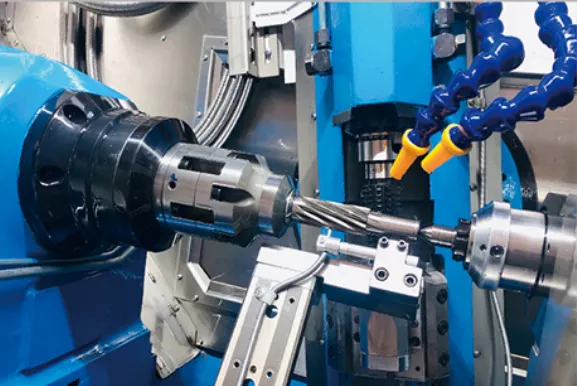
EP-100: direct-drive B/C axes with high-resolution encoder feedback minimise the synchronisation errors that cause pitch deviation
Module Range and Its Effect on Achievable Accuracy
Gear accuracy becomes progressively harder to maintain as module increases. At module M2, a DIN 6 tolerance band on pitch deviation is relatively wide in absolute terms. At module M14, the same DIN 6 tolerance band is wider in absolute terms but the absolute cutting forces, workpiece weight, and chip volume per pass are dramatically higher — and each of these factors degrades the accuracy of a machine that is not specifically engineered for large-module production.
| Module Range | Accuracy Driver | Machine Design Requirement |
|---|---|---|
| M0.5 to M3 | Spindle synchronisation accuracy, hob runout | High-resolution encoders, direct-drive spindle, rigid arbor system |
| M3 to M6 | Thermal stability, table torque | Active thermal compensation, high-torque direct-drive table |
| M6 to M10 | Structural rigidity, table holding force | Heavy-duty bed casting, high table torque, reinforced column |
| M10 to M14 | Machine mass, sustained cutting torque | 14+ ton structure, BT#50 spindle, 2000Nm+ table torque |
DIN Accuracy Classes by Application
| Application | Required DIN Class (Hardened) | Process Required |
|---|---|---|
| Automotive transmission (passenger car) | DIN 5 to DIN 6 | Hobbing + gear grinding |
| EV reduction gear | DIN 5 to DIN 6 | Hobbing + gear grinding |
| Wind turbine main gearbox | DIN 5 to DIN 6 | Hobbing + gear grinding |
| Industrial gearbox (precision) | DIN 6 to DIN 7 | Hobbing + grinding or hobbing + shaving |
| Agricultural / construction equipment | DIN 7 to DIN 9 | Hobbing only |
| General power transmission | DIN 7 to DIN 10 | Hobbing only |
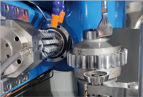
EP-500: maximum capacity M14 / Phi 500mm vertical hobbing for wind turbine main gearbox and heavy industrial gear production
How to Specify Accuracy Requirements When Purchasing a CNC Hobbing Machine
When requesting a machine specification or quotation, the most useful accuracy information to provide is not “we need DIN 6” but the specific gear parameters that matter most for your application, combined with the gear geometry:
Gear Drawing Reference
Module, number of teeth, helix angle, pressure angle, face width. These define the hobbing geometry the machine must execute.
Required Accuracy Class
The DIN class required on the hardened gear — which the supplier must work backward from to determine the pre-grind accuracy target.
Material and Heat Treatment
The material grade and heat treatment process determine the expected post-hardening distortion, which defines the required pre-grind accuracy from hobbing.
Annual Production Volume
High volume applications justify the investment in direct-drive spindles and active thermal compensation that maintain accuracy consistency over many thousands of parts.
All EP-series CNC hobbing machines are supplied with a full machine accuracy report covering B/C axis synchronisation accuracy, Z-axis positioning and repeatability, and spindle runout. Request a sample acceptance test report via the enquiry page when evaluating any machine for precision gear production.
What is the difference between DIN 3962 and DIN 3963?
DIN 3962 covers individual gear accuracy (profile deviation, lead deviation, pitch deviation). DIN 3963 covers tooth thickness and backlash. Both are typically referenced together as part of a gear accuracy specification.
How do I verify that a hobbing machine actually achieves its quoted DIN class?
Request a machine acceptance test report showing CMM-measured gear results on a test gear of known geometry and material. The report should include the measured values of ff, fHα, ffβ, fHβ, fp, and Fp, the tolerance limits for each parameter at the quoted DIN class, and the overall DIN class assignment. If the supplier cannot provide this documentation, the claimed accuracy class is unverified.
Does higher C-axis encoder resolution always mean better pitch accuracy?
Encoder resolution is a necessary but not sufficient condition for pitch accuracy. The mechanical compliance of the C-axis bearing and drive system, the servo control bandwidth, and the stiffness of the workpiece fixture all affect the accuracy with which the workpiece actually follows the commanded angular position, regardless of encoder resolution.
Evaluating CNC hobbing machines for a specific gear accuracy requirement? Submit your gear drawing and DIN class target for a machine selection recommendation and sample accuracy report.