The choice between a direct-drive and a gear-driven spindle system is the single most consequential design decision in a CNC hobbing machine — more consequential than the brand of CNC control, more consequential than the number of axes, and arguably more consequential than the quoted maximum module. Yet it rarely appears in the first page of a machine specification sheet. This article explains exactly how each drive system type affects the gear accuracy you can achieve, why it matters more at some DIN classes than others, and how to evaluate drive system quality when comparing machines.
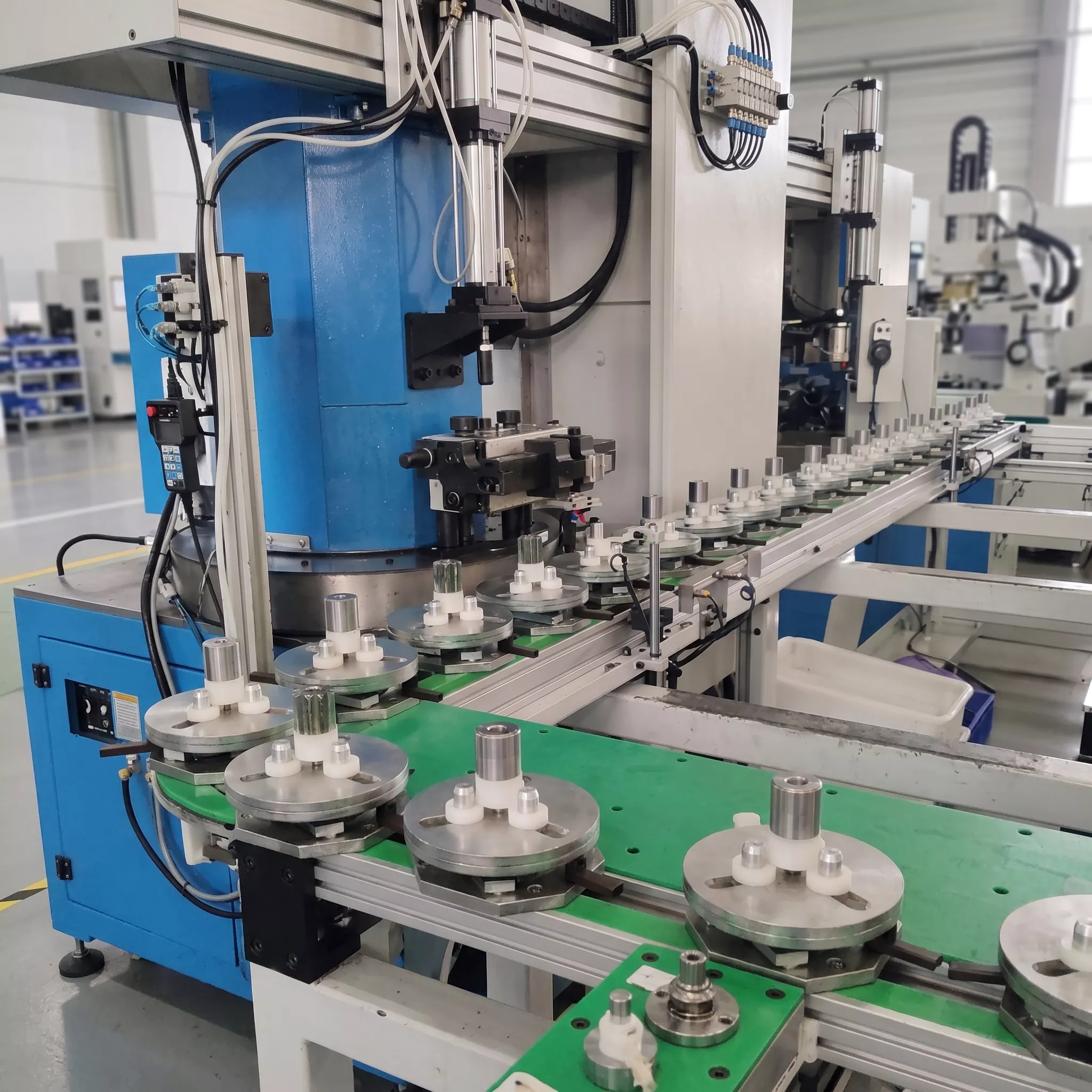
Direct-drive B-axis: the motor rotor is directly attached to the hob spindle. No gearbox, no belt, no coupling — zero mechanical backlash in the drive path
The Transmission Chain: What Creates Gear Errors
To understand why the drive system matters, you need to understand how errors in the hob’s rotation transfer to errors in the gear being cut. The gear hobbing process generates a tooth profile by the continuously accumulated effect of successive hob flute cuts. If the hob’s angular velocity is not perfectly constant — if there is periodic variation in the hob’s speed at any frequency — that variation produces a corresponding periodic variation in the spacing and profile of the cuts, and therefore in the gear tooth form and spacing of the finished workpiece.
In a gear-driven hob spindle, the motor drives a gearbox or belt-and-pulley system that connects to the hob spindle. Every gear mesh in this transmission chain generates a small periodic velocity ripple at the gear mesh frequency (the product of the gear tooth count and the shaft rpm). These ripples are typically small — a fraction of a percent of the nominal speed — but they occur at well-defined frequencies, and the hobbing process amplifies their effect on tooth profile by integrating their contribution across the full cutting engagement.
How Drive System Type Generates Gear Errors
| Error Source | Gear-Driven Spindle | Direct-Drive Spindle |
|---|---|---|
| B-axis backlash | Present — gear mesh clearance in transmission | Zero — no intermediate gearing |
| B-axis speed ripple at gear mesh frequency | Present — produces periodic profile form deviation (ff) | Absent — motor directly controls spindle |
| C-axis backlash | Present if table drive uses intermediate gearing | Zero — direct-drive motor on table |
| C-axis synchronisation error at B/C frequency | Amplified by drive compliance | Minimised — direct motor control of table position |
| Resulting gear error type | Periodic profile form deviation (ff) at hob-rotation frequency; pitch deviation | Random profile scatter; no systematic periodic error |
The DIN Class Boundary Where Drive System Type Becomes Critical
For gear production at DIN 8 to DIN 10 — general industrial gears, agricultural equipment drives, consumer products — the magnitude of gear error introduced by a gear-driven spindle system is typically within the wide tolerance band of these classes. The machine can achieve DIN 8 reliably regardless of whether it uses direct-drive or gear-drive. At these classes, machine selection can legitimately focus on other criteria: module capacity, floor space, or cost.
As the required DIN class tightens toward DIN 6 and DIN 5, the tolerance bands narrow — and the periodic profile deviation generated by gear-driven spindle systems begins to represent a meaningful fraction of the total allowable error budget. At DIN 5 on a module M3 gear, the profile form tolerance (ff) is approximately 5 um. A gear-driven B-axis with even 0.5% speed ripple at 4000rpm will generate a periodic hob velocity variation that, integrated across the cutting engagement, produces profile deviation approaching or exceeding this tolerance.
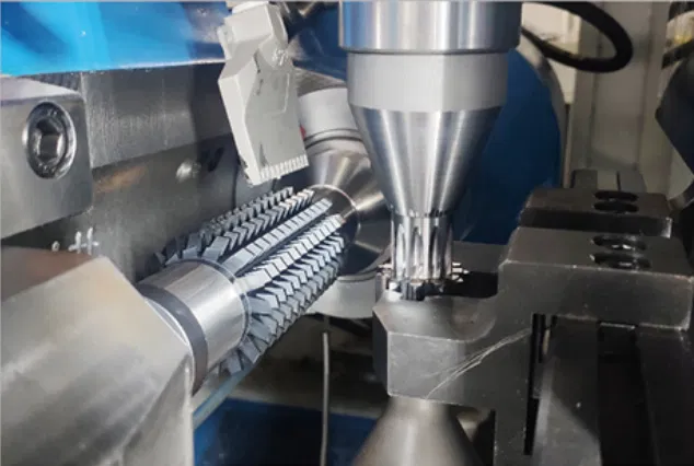
EP-150: permanent magnet synchronous direct-drive spindle — S1=115Nm, S3=143Nm. The direct-drive architecture is the enabling technology for DIN 5 to DIN 6 production at M4.
The C-Axis Table Drive: Equally Important, Less Often Discussed
Most discussion of direct-drive vs gear-driven systems focuses on the B-axis hob spindle. The C-axis rotary table drive system is equally important and less often discussed. The C-axis rotary table must maintain perfect synchronisation with the B-axis throughout the cutting cycle. Any compliance in the C-axis drive — backlash in a worm gear table drive, belt stretch in a belt-driven table — introduces synchronisation lag that directly produces pitch deviation on the gear being cut.
A worm-gear-driven rotary table — still common on older and lower-specification hobbing machines — has a fundamental limitation: the worm gear drive introduces backlash at every reversal, and the compliance of the worm thread under load allows the table to elastically deflect away from its commanded position under the tangential hobbing force. Even with full-circle encoder feedback closing the servo loop, the physical compliance of the worm drive limits the bandwidth of position correction and produces residual synchronisation error.
Direct-drive C-axis tables — where a torque motor’s rotor is directly attached to the table without any intermediate transmission — eliminate both backlash and drive compliance. The servo loop closes on the table position directly, with no compliant element between the encoder and the workpiece. This is why direct-drive C-axis tables consistently produce lower pitch deviation than worm-gear-driven alternatives at the same DIN class target.
Evaluating Drive System Quality When Comparing Machines
When evaluating machines from different suppliers, asking the right questions about drive system type is the fastest way to understand which machines are genuinely capable of your target DIN class:
❓Ask for the B-axis drive type
Is the hob spindle motor directly coupled to the spindle, or is there a gearbox or belt between the motor and spindle? Request a cross-section drawing if the catalogue description is ambiguous.
❓Ask for the C-axis table drive type
Is the rotary table driven by a direct-drive torque motor, or by a worm gear, helical gear, or belt? The table drive type determines the residual pitch error floor of the machine.
Request acceptance test gear results
A DIN 3962 CMM report on a test gear cut by the machine at its quoted DIN class is the most direct evidence of actual gear accuracy capability. If this is not available, the claimed DIN class is unverified.
⚡Ask for S1 and S3 torque data
Both B-axis and C-axis torque should be given as S1 (continuous) and S3 (intermittent) values. If only maximum torque is given without the S1/S3 distinction, ask specifically for the continuous rated torque.
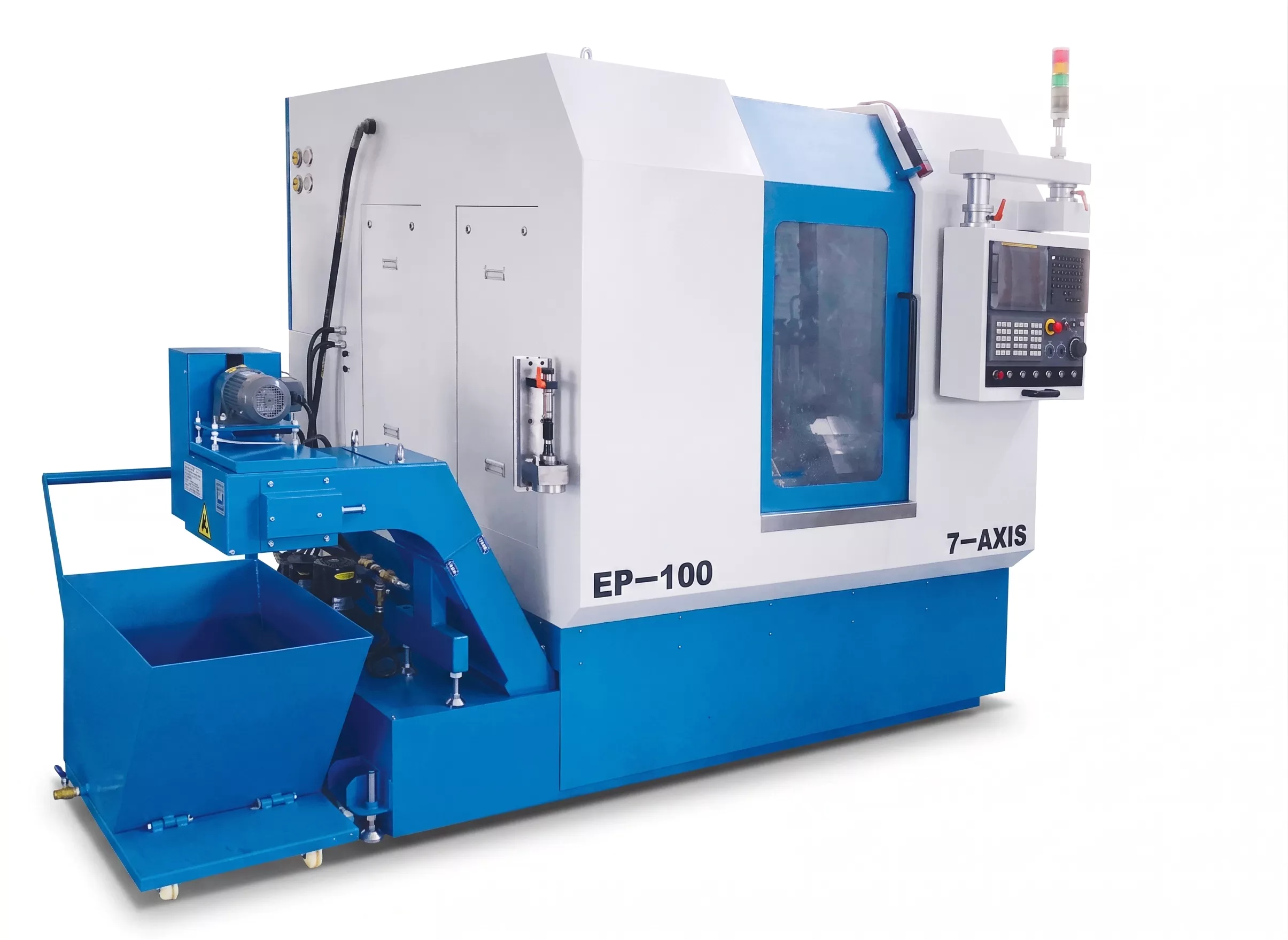
EP-100: direct-drive B and C axes with rotation encoder feedback — the complete direct-drive architecture that enables consistent DIN 5 to DIN 6 on fine-pitch gears to M3
Permanent Magnet Synchronous vs Induction Direct-Drive Motors
Within the direct-drive category, there are two motor technologies in common use on modern hobbing machines: permanent magnet synchronous motors (PMSM) and induction motors. The EP-150 uses a PMSM on the B-axis — this choice affects torque density, thermal characteristics, and servo response:
| Motor Type | Characteristics in Hobbing Applications |
|---|---|
| Permanent Magnet Synchronous (PMSM) | Higher torque density — more torque per unit of motor size. Lower heat generation at rated torque. Higher servo bandwidth — faster response to load disturbances. Better suited to applications requiring high sustained torque at low speed (large module cutting at low rpm). |
| Induction Motor (IM) | Lower torque density — larger motor for same torque output. Higher heat generation at rated torque increases thermal load on machine structure. Lower cost for equivalent power. Suitable for high-speed spindle applications where peak torque duration is short. |
What This Means for Your Machine Purchase Decision
The practical conclusion is straightforward: if your target DIN class is DIN 7 or coarser, drive system type is not a primary selection criterion. If your target DIN class is DIN 5 or DIN 6 on the soft-hobbed gear, direct-drive B and C axes are effectively required — and you should verify this with a supplier-provided CMM test report before purchase, not after delivery.
All EP-series CNC hobbing machines use direct-drive B and C axes as standard. Acceptance test CMM reports showing gear accuracy at the machine’s rated DIN class are available on request via our engineering enquiry page.
Can a gear-driven hobbing machine achieve DIN 6 with careful process control?
In specific conditions — ideal workpiece material, sharp hobs, careful speed optimisation to avoid gear-mesh resonance frequencies — a well-maintained gear-driven machine may occasionally produce parts within DIN 6 tolerance. But it cannot do so consistently and repeatably in production. The periodic profile deviation from gear mesh frequency speed ripple is a systematic error source that cannot be programmed or process-controlled away.
Is a direct-drive machine always more expensive?
Direct-drive motors are more expensive than gearboxes for equivalent torque output. However, direct-drive machines eliminate the maintenance costs associated with gearbox lubrication, gearbox wear, and gearbox backlash adjustment over the machine lifecycle. For production environments targeting DIN 5 to DIN 6 over a 10-year machine life, the total cost of ownership of a direct-drive machine is often lower than the sum of initial cost plus maintenance cost of a gear-driven alternative.
How do I verify drive system type from a machine specification sheet?
Look for the B-axis and C-axis motor descriptions. Terms such as “direct drive,” “torque motor,” “DDR motor,” or “built-in motor” indicate direct drive. Terms such as “servo motor,” “AC spindle motor,” or “servo with reducer” indicate an intermediate transmission. If the specification sheet does not clearly state the drive type, ask the supplier directly for a schematic of the B-axis and C-axis drive trains.
Evaluating CNC hobbing machines for DIN 5 to DIN 6 production? Ask us for a sample acceptance test gear report showing measured ff, fp, and Fp values on a production test gear.